X2 Omnipicker Installation
Recommended Reading
Official OmniPicker Product Manual
- Official link
- Product Overview
- Specifications & Parameters
- Dimensions
- OmniPicker Gripper Operation Tutorial(Chinese, English soon)
‼️Safety Precautions
- Never disassemble, adjust, or repair the device while the robot is operating or powered on, to prevent damage or safety hazards.
- Always work on a clean, dry, well-lit, and ESD-protected workbench.
- Power off the robot before any disassembly or assembly operation.
- Use insulated tools and wear appropriate PPE: anti-static wrist strap, safety glasses, and cut-resistant/insulating gloves.
- Visit the AgiBot official website for full product terms and policies.
- Comply with all applicable local laws and regulations. Do not modify or operate the robot in any hazardous manner.
Tools required
| # | Tool | Spec |
|---|---|---|
| 1 | Hex Key | H2.0, 2.5, 3.0 |
| 2 | Wire Harness | 1.25mm Pitch, 6-pin |
Removing the dummy hand
The X2 ships with a dummy hand installed by default. Before mounting the gripper, the dummy hand must be removed first.
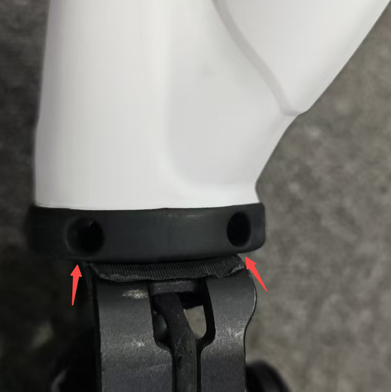
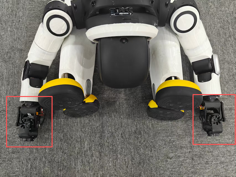
OmniPicker gripper assembly
Important
- The OmniPicker gripper has no left/right distinction, but it has a required orientation: small palm faces inward, large palm faces outward.
- The OmniPicker adapter brackets are left/right specific. Before installation, confirm the correct orientation of both the gripper and adapter relative to the robot. Refer to the orientation diagram below.
- If the gripper is not in its original packaging, skip this section and proceed directly to Mounting onto the Robot.
Each gripper ships with: 2× Gripper, 2× Adapter Bracket, 2× Wire Harness
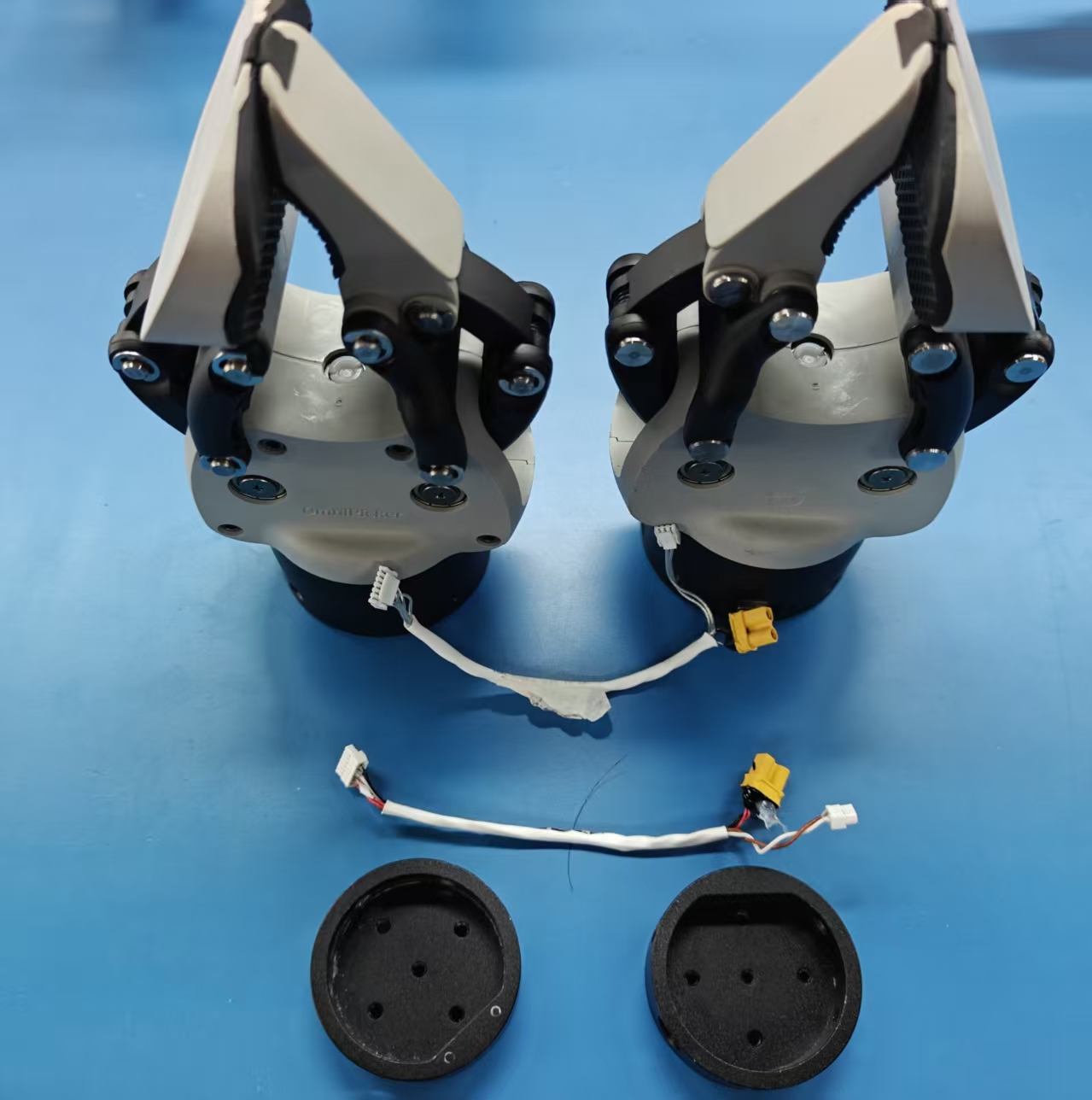
Step 1 — Open the gripper cover
Remove the four screws on the gripper cover and open it.
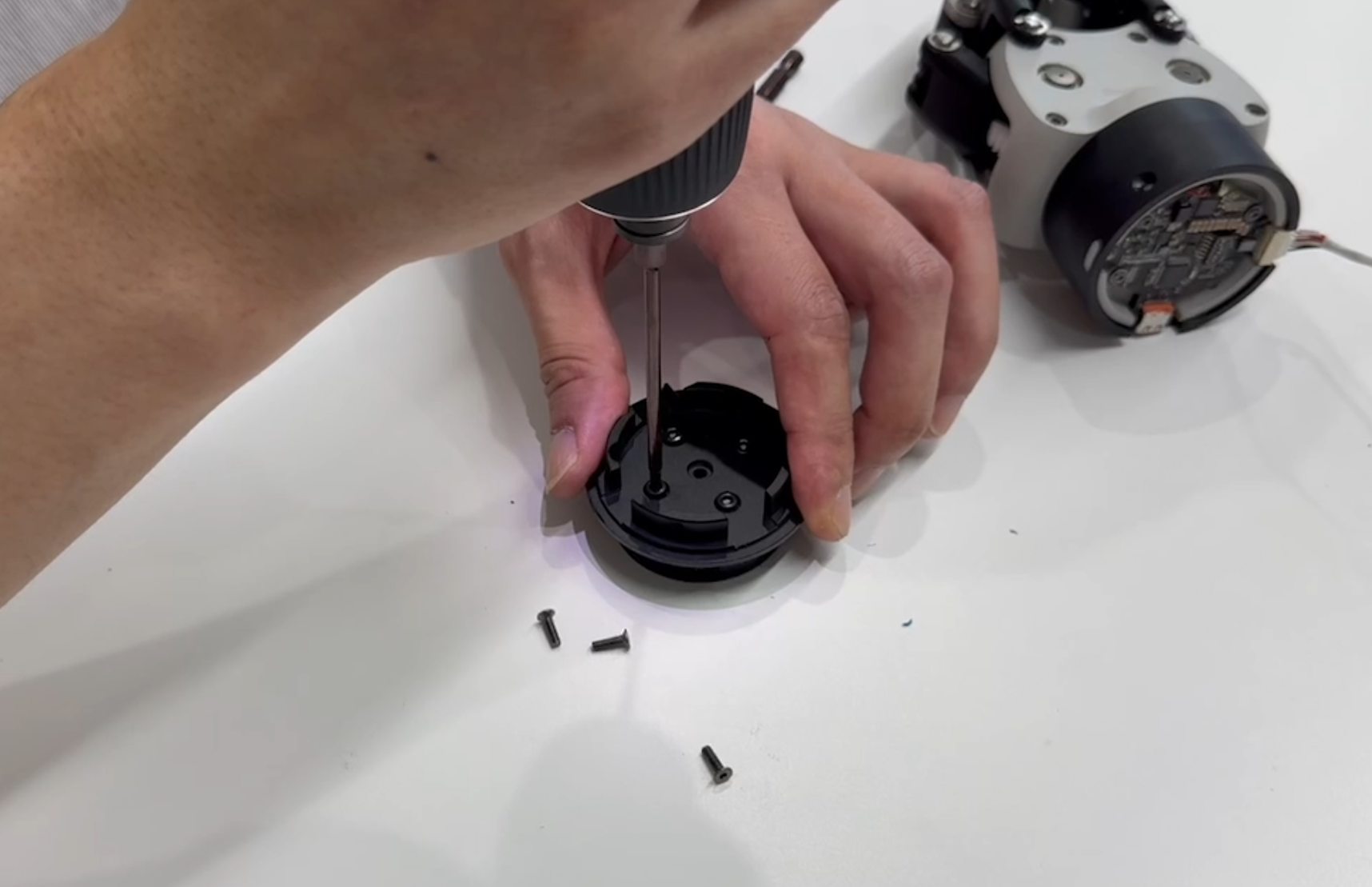
Step 2 — Attach gripper cover to adapter bracket
Align the screw holes on the gripper cover with those on the adapter bracket. Insert five screws (M3x6) from the back and tighten them one by one using H2.5.
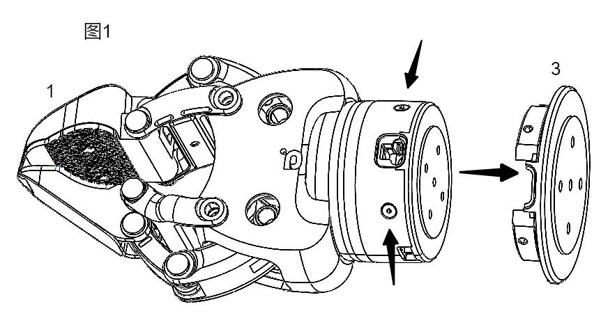
Step 3 — Reattach the gripper cover
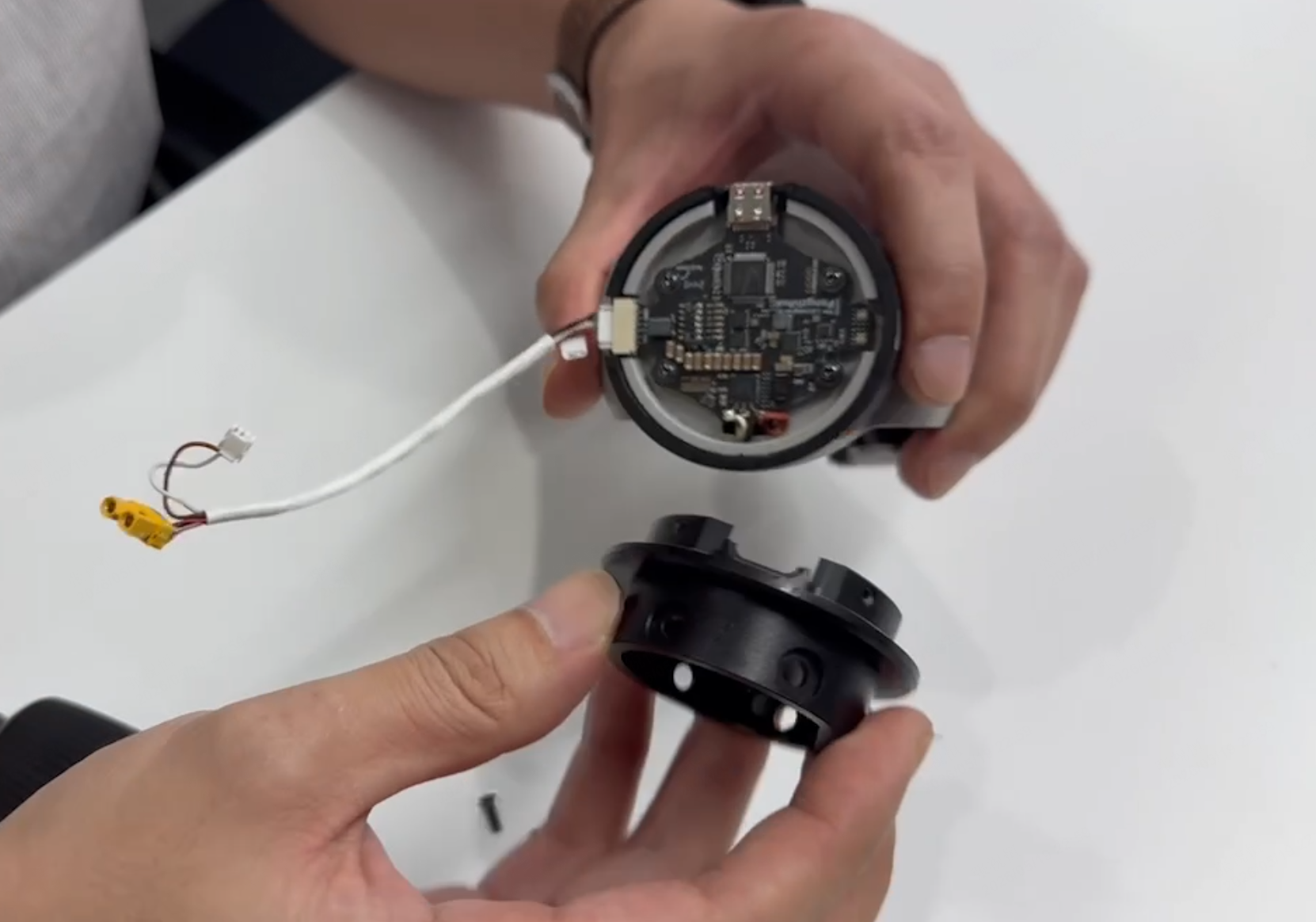
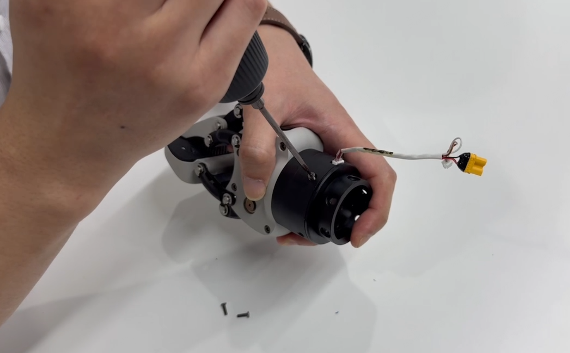
Align the gripper cover with the gripper interface, fasten with 4 screws, and tighten them one by one. See this image for reference.
Mounting onto the Robot
Important
- Do not pinch any cables during installation to avoid damage and poor contact.
- If the gripper is brand new (taken from its packaging box), complete the Gripper Assembly steps above first.
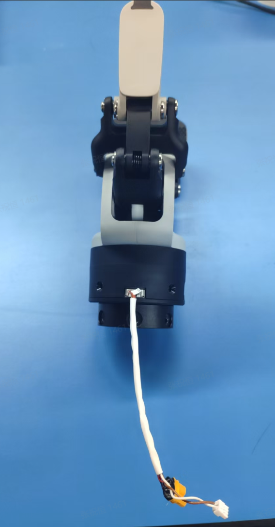
Step 1 — Connect wire harness to gripper
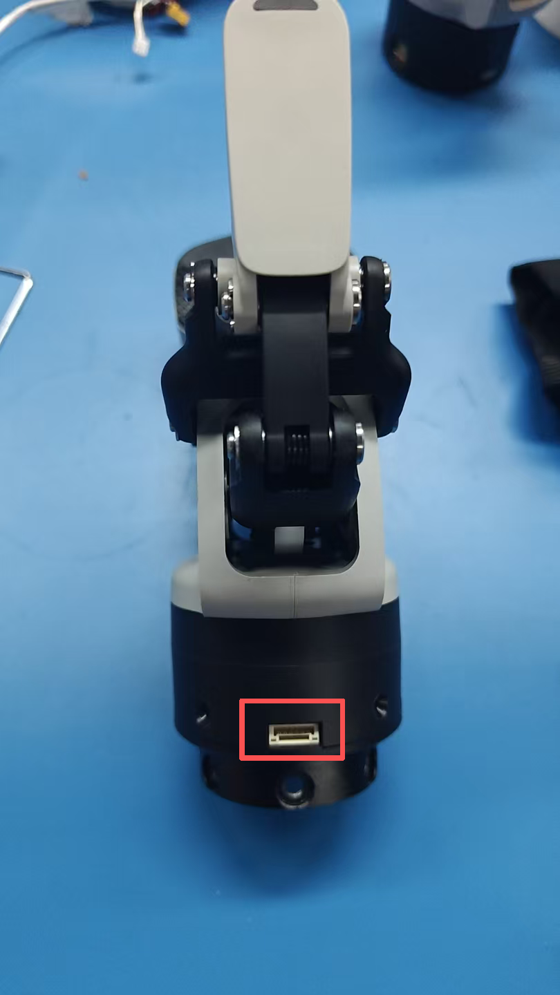
Using one gripper as an example: insert the single-connector end of the wire harness into the port marked on the gripper in the diagram below.
Step 2 — Mount gripper onto robot
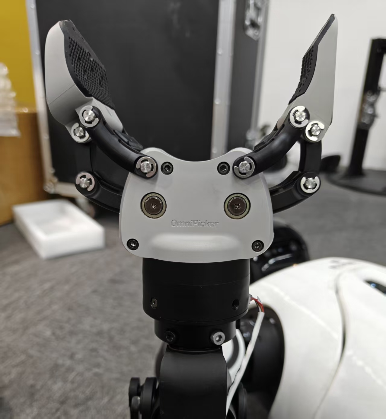
Orientation: small palm faces inward, large palm faces outward.
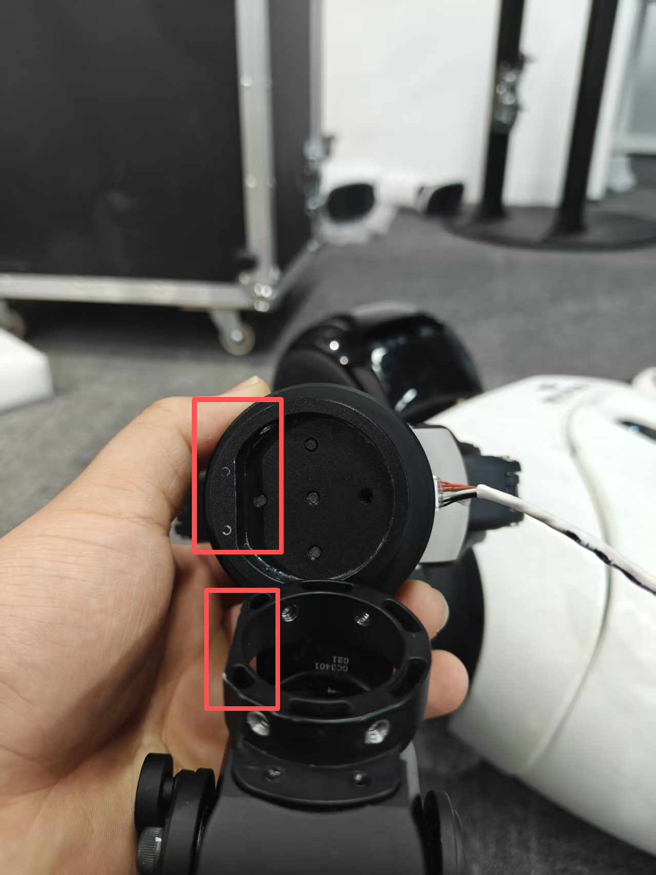
Align the flat edge of the adapter bracket with the flat edge of the X2 wrist joint. Once aligned, slide the gripper downward into position and secure with screws (M4x8) using H3.0.
Step 3 — Connect wire harness to wrist motor
Note: The robot must be powered off before wiring. Never perform wiring while the robot is powered on.
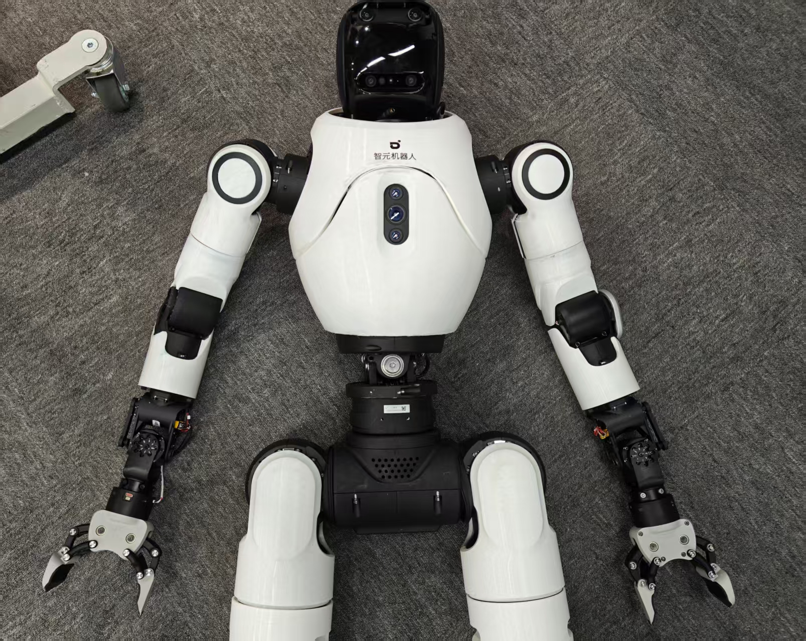
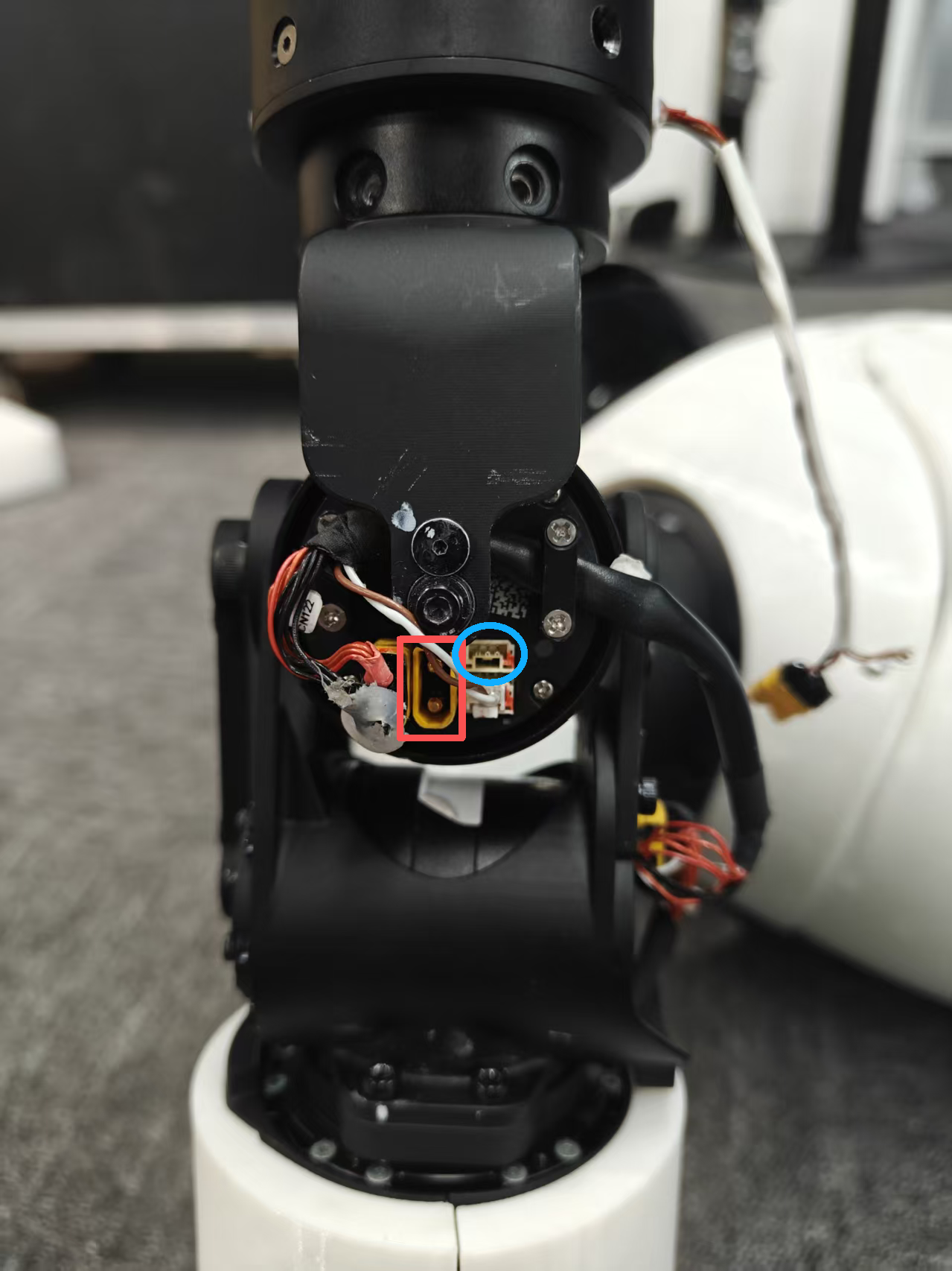
After the gripper is mounted, remove and safely store the existing terminal resistor before connecting, then connect the two remaining wire harness ends:
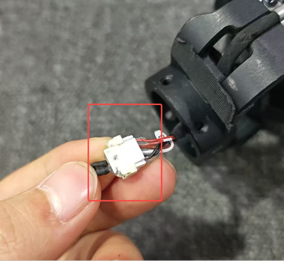
- Yellow wire → Robot wrist J7 motor (red box position in the diagram)
- White wire → Blue circle position in the diagram ()
Repeat the same steps for the other gripper.
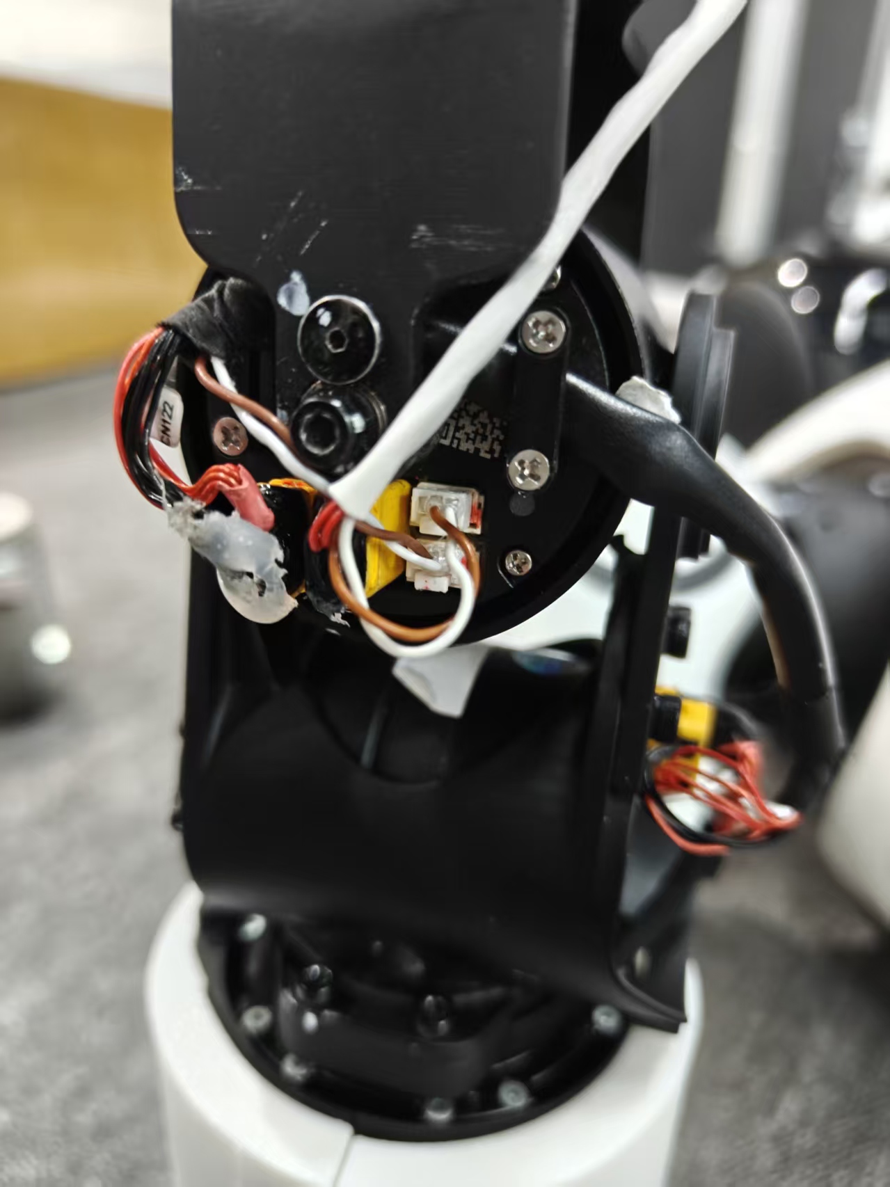
Your Omnipickers are ready.
Read Next
Products
X2 Omnihand Installation