X2 Calibration
Recommended Reading
Must Read Before Use
- Applicable Versions: 0.8 / 0.9 / 1.0
- Applicable Models: Flagship / Youth Edition (When performing zero calibration on the X2 Lite, you must switch the software configuration IP.)
- Purpose of Zero Calibration: Humanoid robot joint zero calibration is used to re-establish the mechanical zero reference point, eliminate encoder drift and cumulative errors, unify the coordinate systems of multiple joints, and ensure motion accuracy, movement consistency, and safe and stable operation.
- Tool Preparation:
- Upper limbs: No fixtures or pins required; calibration can be performed on-site directly.
- Lower limbs: Requires a 2mm calibration pin to complete calibration.
- Waist: Requires a dedicated waist fixture. On-site operation is difficult; factory return is required for calibration.
Preparations
Tools to prepare before calibration:
| No. | Name | Qty | Notes |
|---|---|---|---|
| 1 | 2mm pin gauge / feeler gauge | 2 | Only needed for legs |
| 2 | 3mm pin gauge / feeler gauge | 1 | Only needed for legs |
| 3 | Computer / Laptop | 1 | Windows system required |
| 4 | Ethernet cable | 1 | Recommended 1m or longer |
| 5 | Patient lift / transfer device | 1 | Optional but convenient for calibration; contact after-sales service to purchase if needed |
Install dependency packages
Download from this link, unzip to install the programs. Missing dependencies may prevent the software from launching.
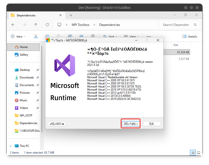
- Install
MSVBCRT64-8.3.0
- Open the program and grant the permission.
- Click the red button below three times to install.
- Close the program after installation.
- Install
NDP461-KB3102436-x86-x64-AllOS-CHS
- Open the program.
- If the interface looks like the one shown below, no installation is required; please skip this dependency. Otherwise, follow the steps below.
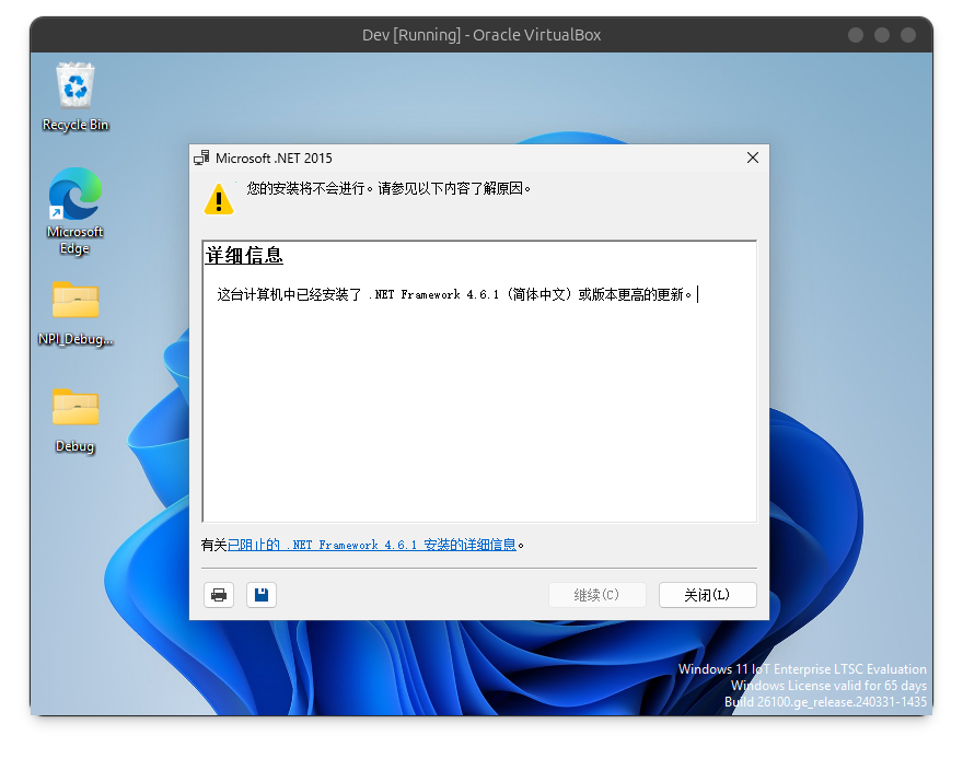
- Click “Next” to install the program.
NPI Toolbox
Install the toolbox
- Connect your host PC to the Internet to use this tool.
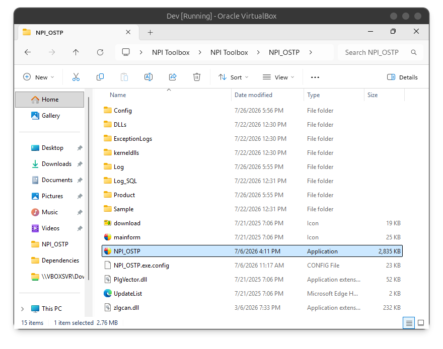
- Unzip the NPI Toolbox to the D: drive. Double click
NPI_OSTP.exeto open it.
- Connect the host PC to the Robot via Ethernet cable. Denpending on the device under test, config your host to one of the following ip in the subnet. For example, steps:
- Open network panel;
- Change from automatic to manual;
- Set IP to
10.0.1.99(Ultra)10.0.200.99(Lite), subnet mask to255.255.255.0
| Edition | IP/Subnet | Note |
|---|---|---|
| X2 Lite | 10.0.200.XX/24 | Open the software and use it directly — no additional configuration needed. |
| X2 Ultra | 10.0.1.XX/24 | Follow the steps for each module. |
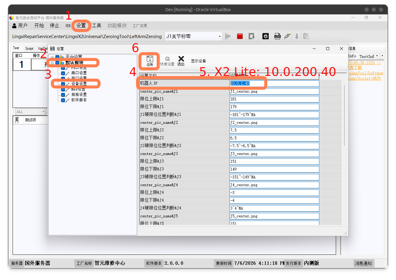
Configuration for X2 Lite
If your device is X2 Lite, you must enter the software configuration interface to switch settings. The specific steps are as follows (this must be reconfigured each time you select a different calibration module).
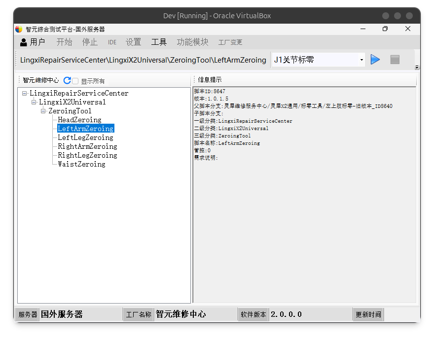
After downloading, follow the steps in the following screenshot below to config the calibration module.
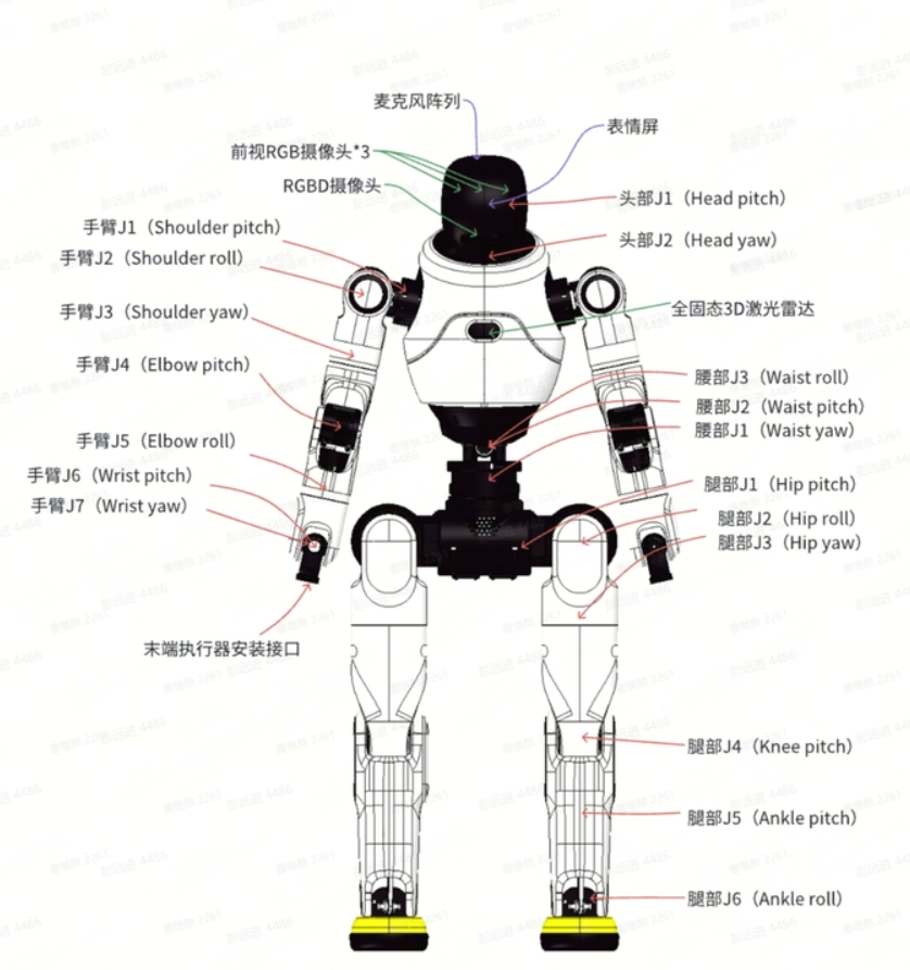
Robot Joint Diagram
Note: When calibrating limb joints, if a patient lift is not available to suspend the robot, it is recommended to calibrate with the robot lying flat or sitting upright.
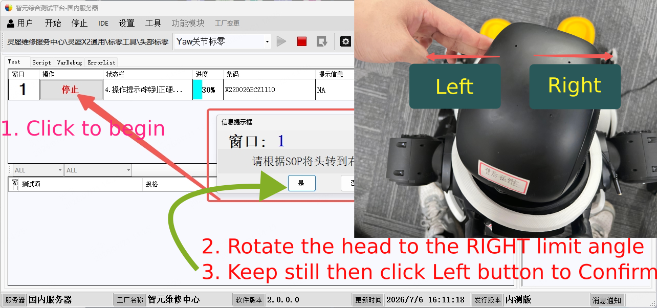
Head Calibration
Double click to open the HeadZeroing module.
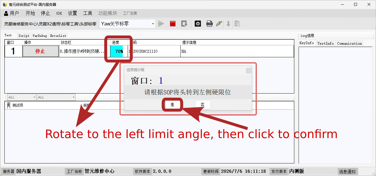
As shown below, stand behind the robot. The left/right orientation matches the user’s perspective. Twist the robot’s head to the limit and hold it in place. Click left button and wait for the robot to respond with a “beep-beep-boop” sound, then observe the software prompt changes. Rotate to the right limit angle firstly and confirm (or ENTER⤶).
Then rotate to the left limit angle.
Click 🟥 to exit when it is 100%.
Upper Limb Calibration
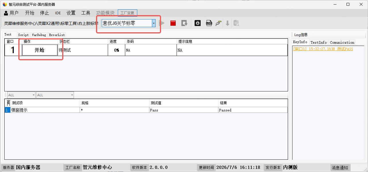
Double click to open the Left/RightArmZeroing module. Enter the right upper limb calibration. The program interface defaults to starting calibration from the J1 joint. (If you only need to calibrate specific joints, select the required joint directly.)
The image below shows how to switch calibration joints:
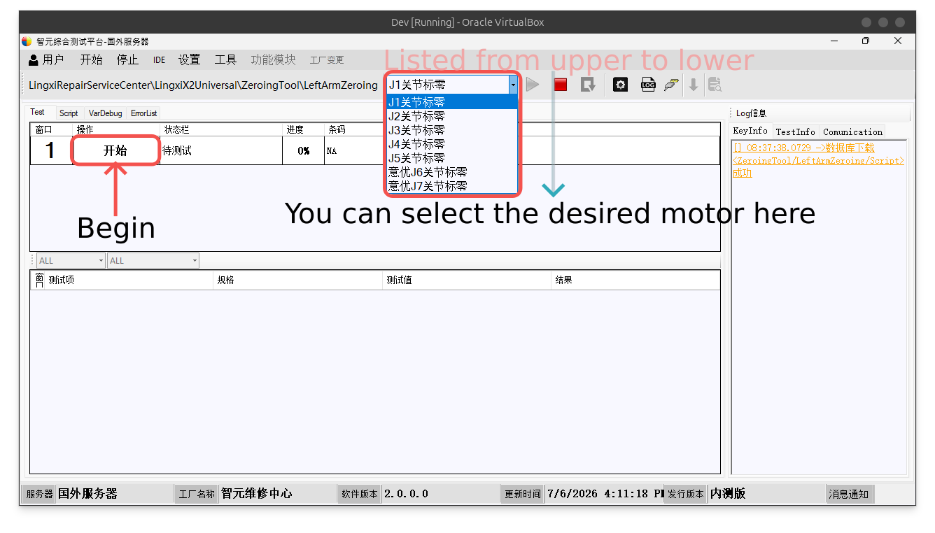
In the following context, we will start with the right arm calibration.
J1
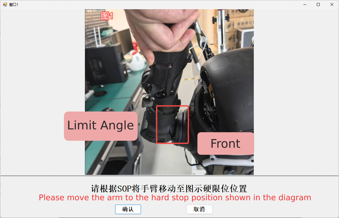
Then move to the center position and hold it, then click the left button to confirm(or ENTER⤶).
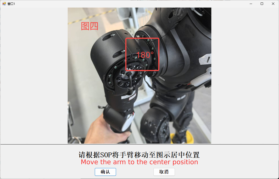
Move the arm to 180° (right arm), -180° for left arm
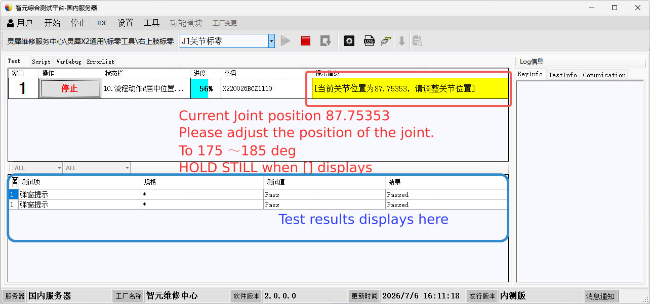
When success, refer to the picture above back to the limit angle to finish the last step.
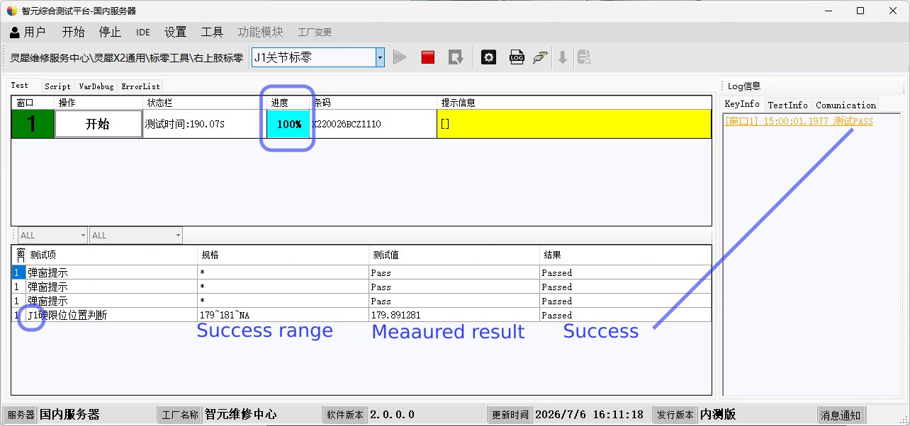
Note: If calibration fails, simply restart the above steps.
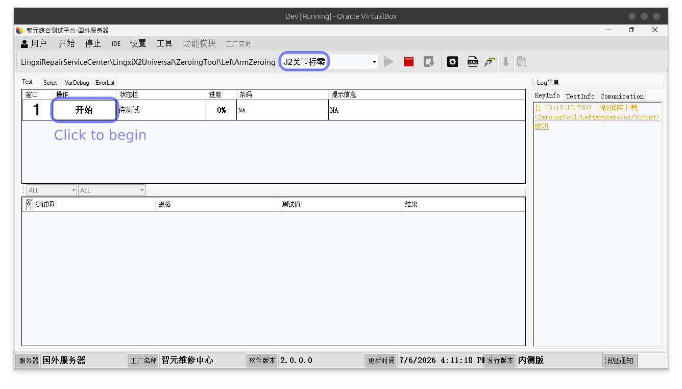
J2
Select J2 from the dropdown, then click the flowing button to begin.
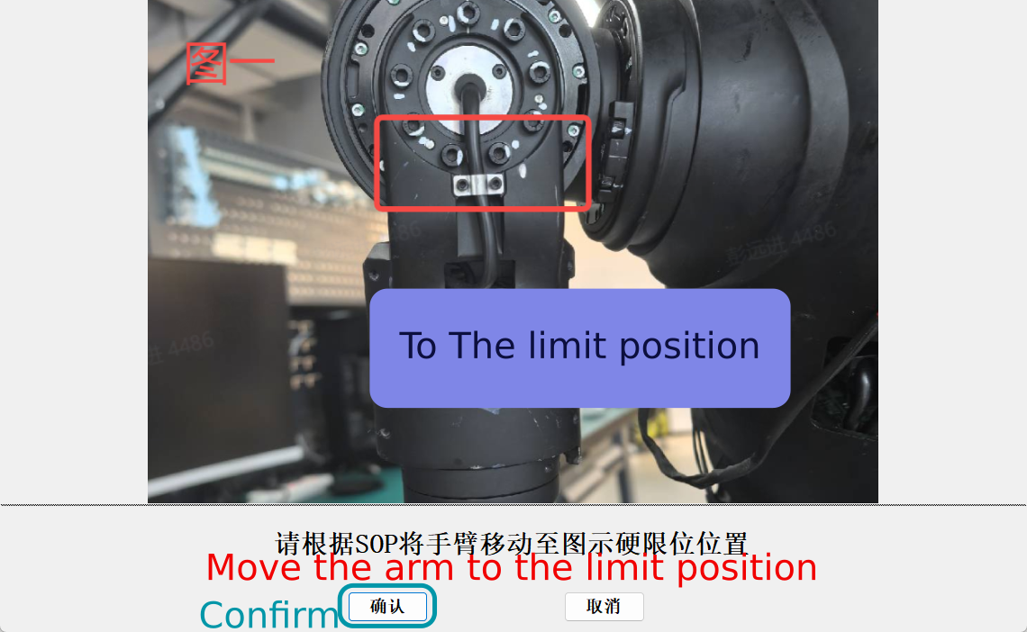
Regarding to the prompt, move the J2 to the armpit limit position. Hold the pose still and press Enter to confirm(or ENTER⤶).
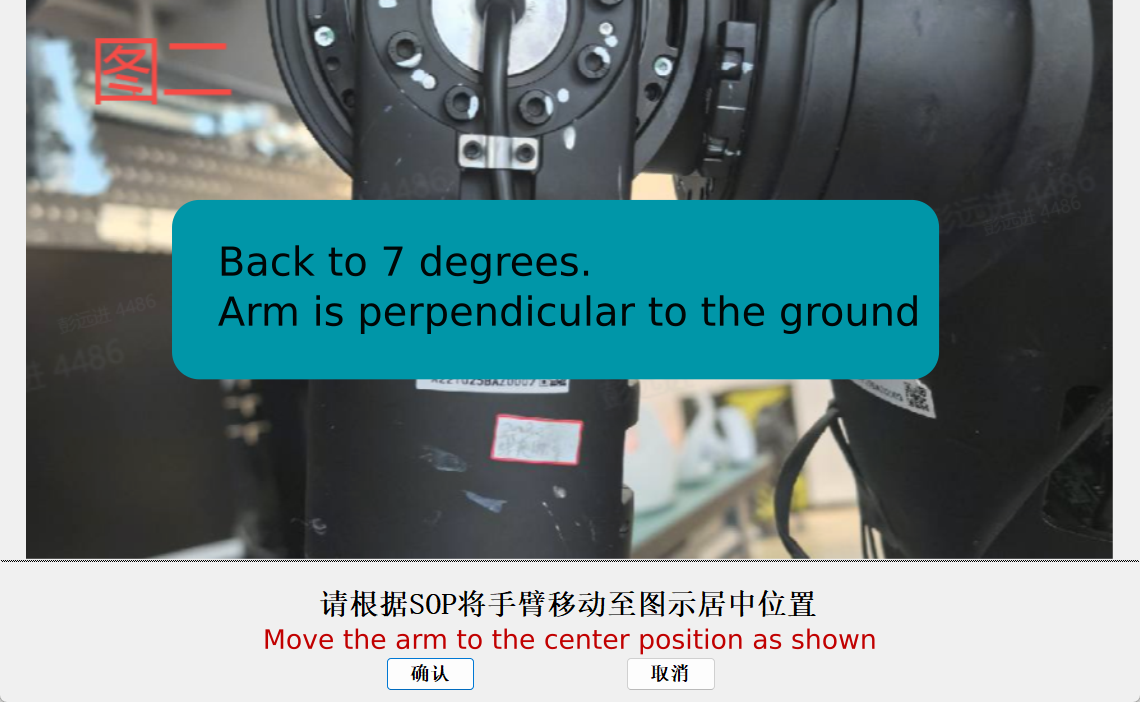
Move the arm to the center position, you can read from text box to get 7°, -7° for the left arm.
Then follow the steps to move the J2 to the limit angle as shown above. Once [] appears, hold still, wait for 100% & pass.
J3
Select J3 from the dropdown, then click the flowing button to begin.
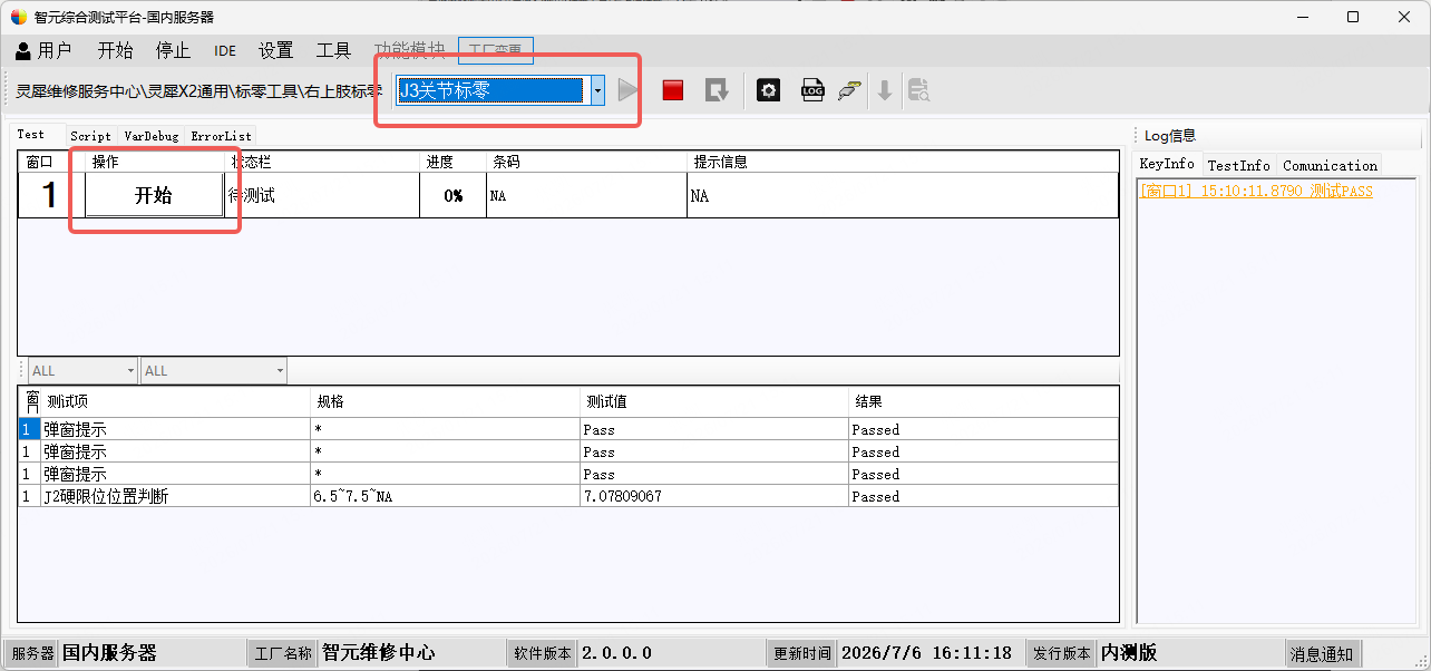
The first prompt will look like the following. Twist the robot J3 to the prompted position, press ENTER⤶, and hold the pose still.
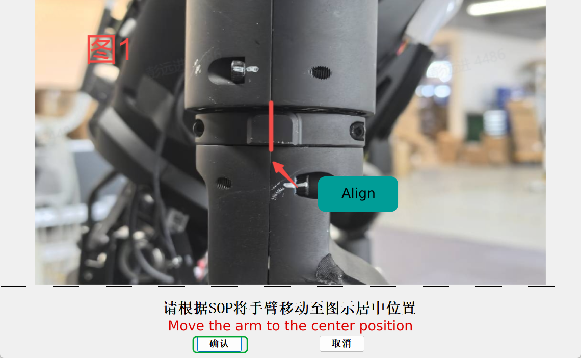
Wait for the prompt tone and the pass to appear — J3 calibration is then successful.
J4
Select J4 from the dropdown, then click the flowing button to begin.
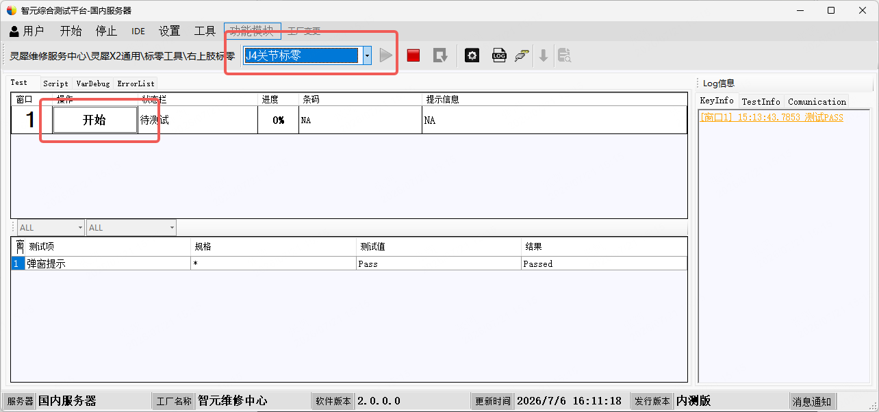
Push J4 backward to hard limit shown in the diagram below.
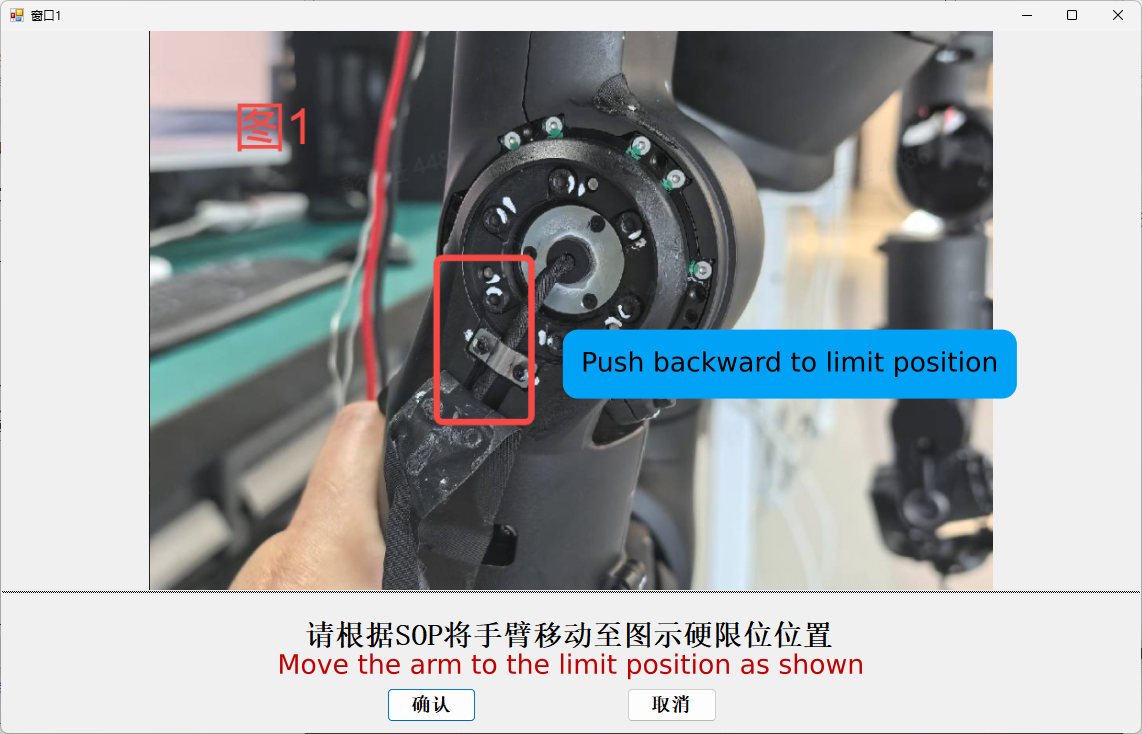
Press ENTER⤶ or click the button to confirm, when [] appears, hold still. Then one another prompt shows up:
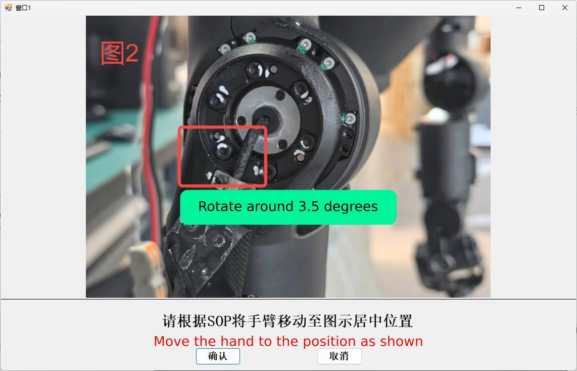
When [] appears, hold still. Then the prompt will show like the above, let the J4 back to the limit position. Confirm (ENTER⤶) and wait []
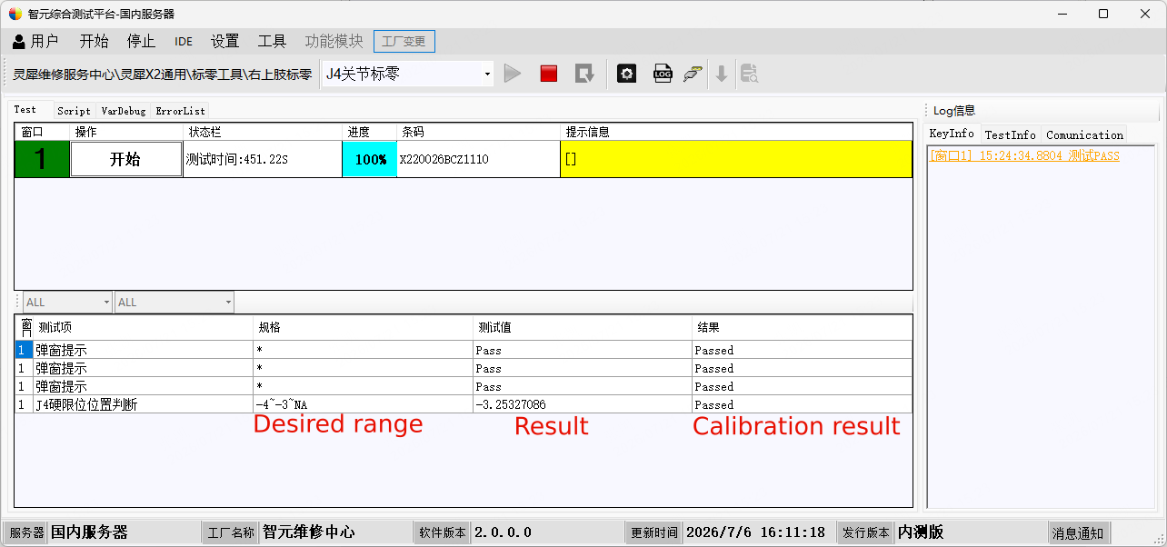
Wait for the prompt tone and the pass to appear — J4 calibration is then successful.
J5
Switch from “J4” to “J5”, then click the “Start” button on the left.
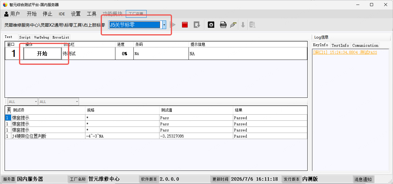
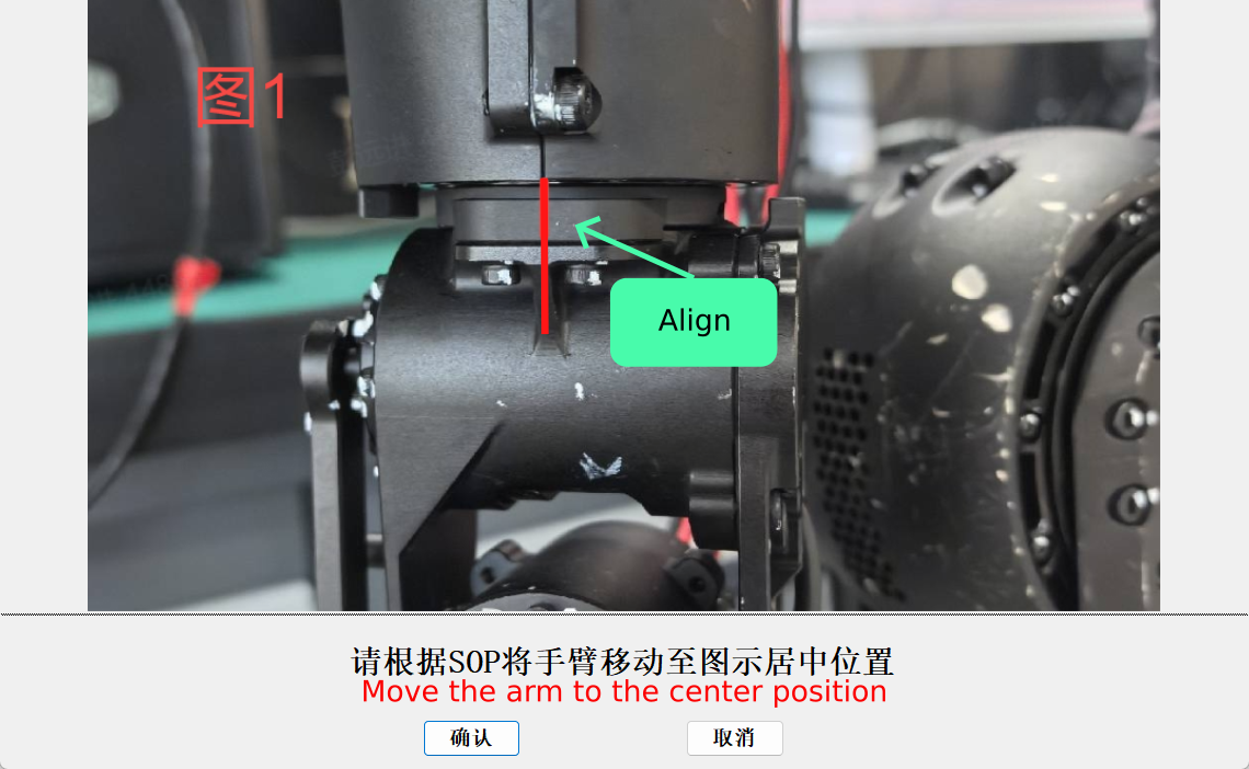
Push J4 to the center shown in the diagram below, hold still, and press ENTER⤶ to wait showing progress 100%, prompt [] and pass.
Note for J6 and J7
The new tool currently has issues with arm joints J6 and J7 calibration. R&D is working on a fix — please be patient.
J6
Switch from “J5” to “J6”, then click the “Start” button on the left.
Locate the two screws at the J5–J6 joint connection as shown below (used as a reference marker), then twist the J6 motor in the opposite direction from the marker to the limit position, hold still, and press Enter to confirm.
![Press ENTER⤶ to confirm, hold still when [] appears.](/images/J6-2.png)
While watching the system’s “Prompt Information”, slowly twist the J6 motor to -33°. When the prompt shows ”[]”, immediately hold still. Then follow the following prompt, rotate the joint to the left limit position:
![Press ENTER⤶ to confirm, hold still when [] appears.](/images/J6-4.png)
Wait [] and pass appear.
J7
Switch from “J6” to “J7”, then click the “Start” button on the left.
As shown below, twist the J7 motor to the connecting rod direction limit position, hold still, and wait for the system response.
![Press ENTER⤶ to confirm, hold still when [] appears.](/images/J7.png)
After the response, you will hear the “beep-beep-boop” prompt tone and the pass appears.
Lower Limb Calibration
Click 🟥 to back to the home page, double click to open the Left/RightLegZeroing module. Inside the module, you can select the joint from the dropdown.
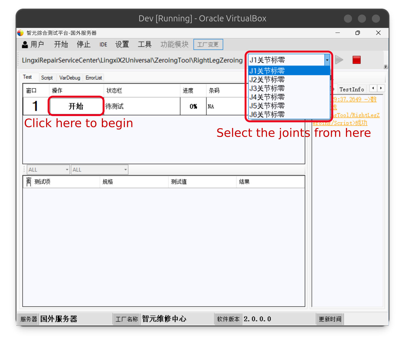
J1
Switch to “J1”, then click the “Start” button on the left.
Insert the positioning pin into the positioning hole of the J1 joint. If the J1 motor remains stationary when you rock the joint back and forth, the positioning pin is fully seated.
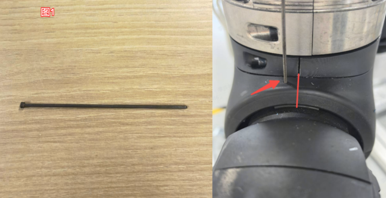
You can take the positioning pin out after calibration.
J2
Switch from “J1” to “J2”, then click the “Start” button on the left.
It’s almost the same with the joint J1. Insert the positioning pin into the positioning hole of the J2 joint(shown below). If the J2 motor remains stationary when you rock the joint back and forth, the positioning pin is fully seated.
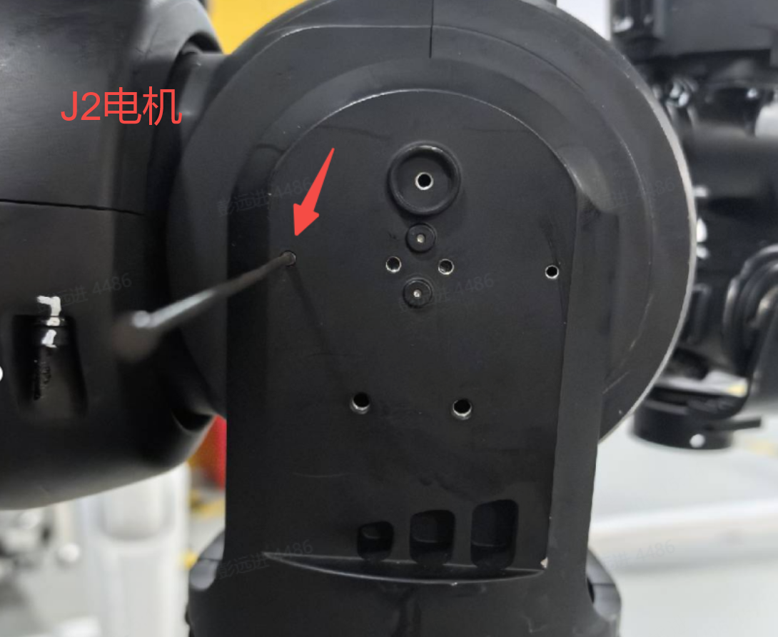
You can take the positioning pin out after calibration.
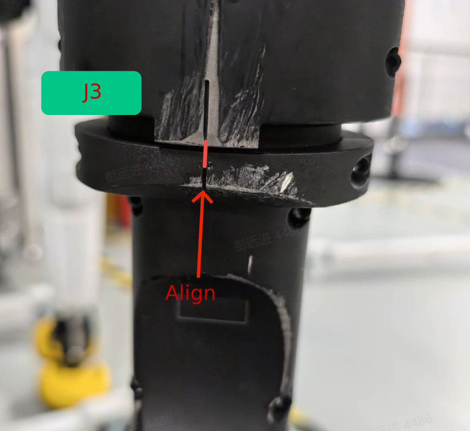
J3
Switch from “J2” to “J3”, then click the “Start” button on the left. Align the J3 with the J2 according to the picture below:
J4
Switch from “J3” to “J4”, then click the “Start” button on the left.
Insert the positioning pin into the positioning hole of the J4 joint(shown below).If the J4 motor remains stationary when you rock the joint back and forth, the positioning pin is fully seated.
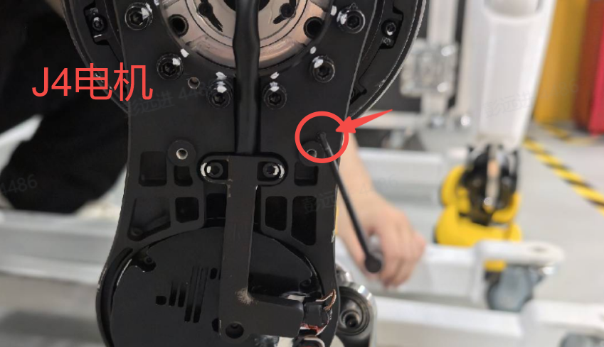
You can take the positioning pin out after calibration.
J5
Switch from “J4” to “J5”, then click the “Start” button on the left.
Insert the positioning pin into the positioning hole of the J5 joint(shown below). If the J5 motor remains stationary when you rock the joint back and forth, the positioning pin is fully seated.
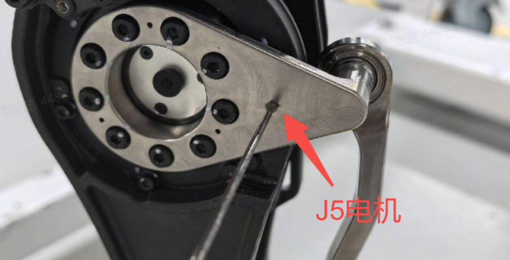
You can take the positioning pin out after calibration.
J6
Switch from “J5” to “J6”, then click the “Start” button on the left.
Insert the positioning pin into the positioning hole of the J6 joint(shown below). If the J6 motor remains stationary when you rock the joint back and forth, the positioning pin is fully seated.
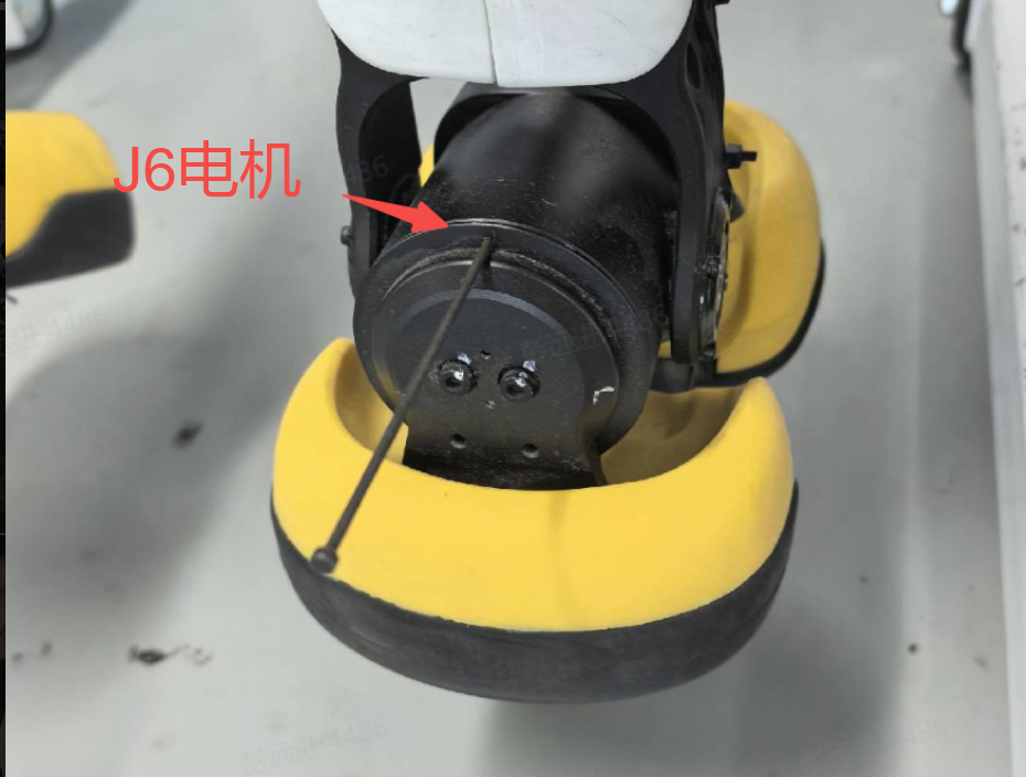
You can take the positioning pin out after calibration.
Waist
Requires a dedicated waist fixture. On-site operation is difficult; factory return is required for calibration.